
Designing a Rigid-Flex Printed Circuit Board
With the advent of wearables and flexible electronics, rigid-flex printed circuit boards are becoming increasingly essential to the manufacturing process. These PCBs enable products to flex, fold, and bend, while providing high reliability and mechanical stability. However, the complexities that arise from the unique design of rigid-flex boards require specific attention and careful consideration.
One of the primary challenges in designing a rigid-flex board is ensuring that there is a smooth transition between the rigid and flexible portions of the circuit board. This is important to prevent mechanical stress that can cause signal degradation and electrical performance issues. Connector placement is also critical, as poor connector placement can lead to flexing, mechanical stress, and reliability problems. Finally, the correct layer transition between rigid and flexible sections is crucial to maintaining signal integrity and preventing electromagnetic interference (EMI).
rigid-flex printed circuit board typically have a higher number of layers than traditional rigid PCBs, making them more complex to fabricate. This complexity can increase manufacturing costs, as a fabricator must spend more time and resources on the lamination process. Choosing the right materials is also critical to reducing the cost of rigid-flex PCBs. For example, selecting a low-cost rigid material like woven fiberglass with epoxy resin could save money on the cost of production. However, this may not provide the durability required for harsh environments like automotive or aerospace applications.
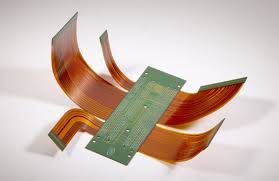
Challenges in Designing a Rigid-Flex Printed Circuit Board
Another challenge of rigid-flex PCBs is ensuring the reliability of solder joints in areas subject to bending or flexing. This can be challenging because the conductive paths on a flex circuit must pass through multiple layers of the PCB, and it is difficult to achieve high-quality solder joints with such a large number of connections in tight spaces.
To minimize this issue, designers should ensure that the flex circuit has a wide enough trace width to support the required conductive path length. They should also avoid placing components or vias close to the bending edge, as this can create mechanical stress. Rigid-flex PCBs should use hatched copper plating to maintain flexibility and reduce the number of vias, as these can easily crack under pressure.
Other challenges of rigid-flex PCBs include the need to accommodate thermal management, the impact of flexing on signal integrity and electromagnetic interference (EMI), and determining the best way to transfer heat between the rigid and flex sections of the circuit board. Rigid-flex circuits can be made more durable and reliable by using a rigid material that is a good thermal conductor, such as polyimide.
A well-designed rigid-flex circuit board can be used in a wide range of applications and is an excellent choice for wearables, consumer electronics, medical devices, and aerospace systems. However, to produce a robust and reliable rigid-flex circuit board, it is important to consider the unique requirements of your application and bring an experienced electronic contract manufacturer onboard early in the design phase. An ECM can offer design iterations, prototyping, and advanced manufacturing capabilities to produce a rigid-flex circuit that meets your specifications and performance goals.